
DESIGN TO ASSEMBLY
ENGINEERING SERVICES
Our experts in rugged product engineering will work with you to design a solution purpose built for your mission. The Core Systems Engineering Team provides a complete suite of solutions for cradle-to-grave rugged product design and engineering support.
- CUSTOM DESIGN
- FABRICATION
- TESTING
- ASSEMBLY
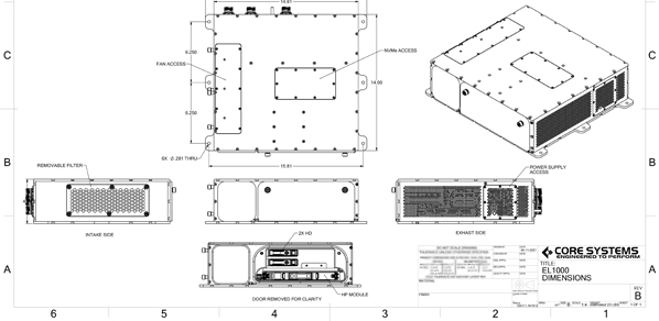
OUR DESIGNS
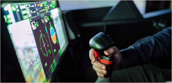
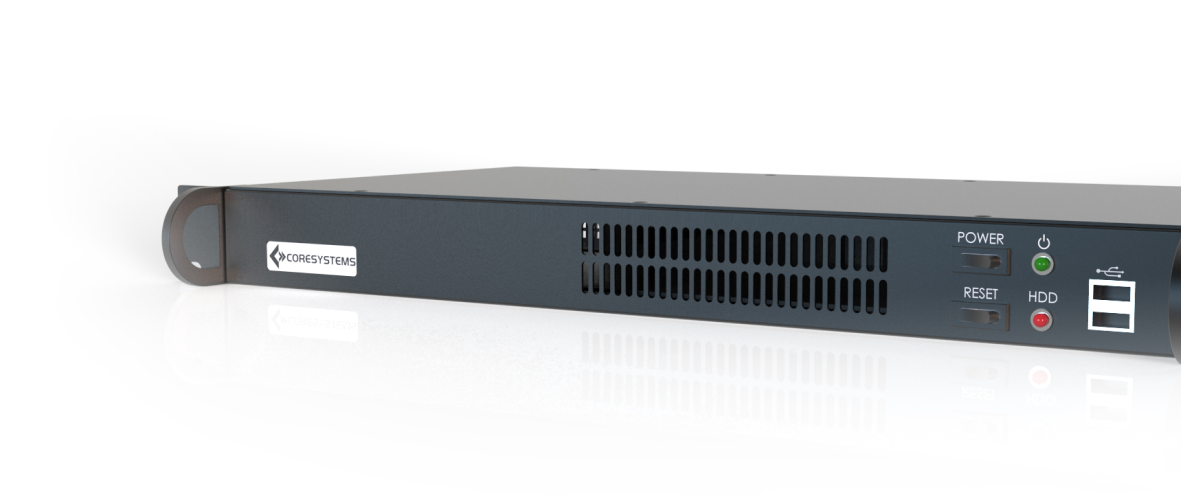
RUGGED COMPUTING SOLUTIONS
Core Systems works with you to design and configure both COTS and custom, rugged and industrial computing solutions that are built-to-order. We can produce quick-turn modifications to existing product designs or complete ground-up, application-specific rugged designs built for your mission.
- RUGGED SERVERS
- RUGGED DISPLAYS
- RUGGED TRANSIT SUITES
- RUGGED MISSION COMPUTERS
QUICK TURNAROUND
OUR PROCESS
Planning
We work with you to discover your rugged system needs for your mission.
Custom Design
Our experienced engineers will design your system based on your specifications.
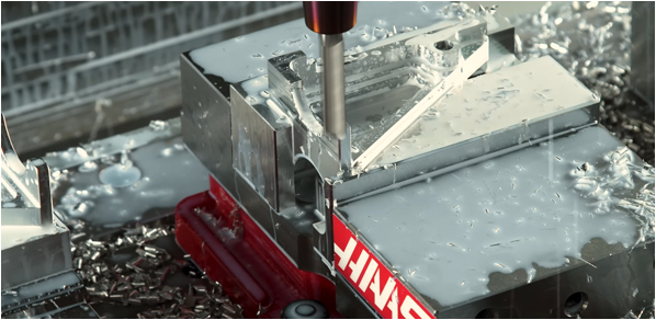
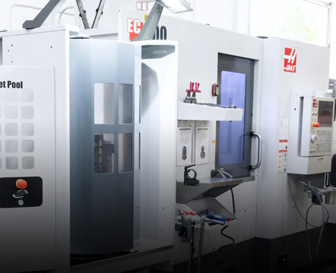
Fabrication
Our on-site metal shop allows us to build parts on the fly in order to ensure quick turnaround.
Integration
The assembly process includes system integration, robotic potting, conformal coating, etc.
Testing
We test our systems to meet the environmental standards needed to meet for your mission.
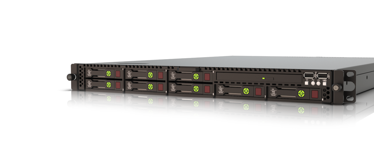
RUGGED HPE
Our partnership with HPE allows us to deliver rugged, cutting-edge HPE designs that can be built to work alongside other networking and storage options.
- RUGGED CHASSIS
- SHORT-DEPTH SOLUTIONS
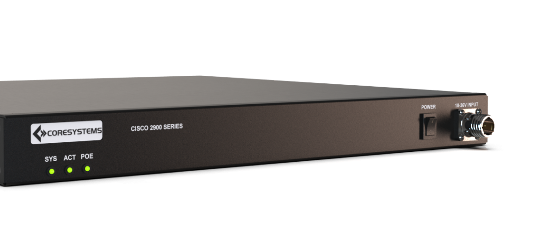
RUGGED CISCO
Complex networking solutions for the military require rugged CISCO routers, switches and routers that are transit-ready and application-specific.
- CISCO NETWORKING
- MIL-SPEC TESTED
INDUSTRIAL SOLUTIONS
For industrial needs we develop and deliver complete industrial systems that improve power, speed and storage for your business.
- INDUSTRIAL-GRADE
- ENHANCED DURABILITY
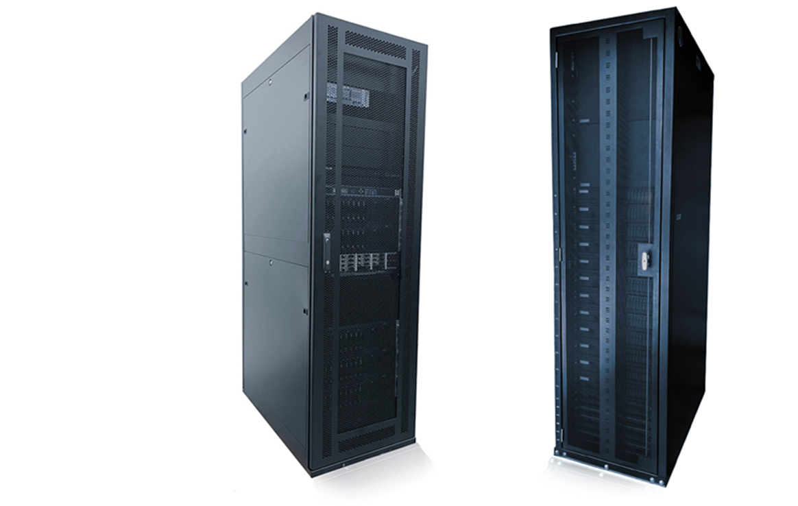
RACK INTEGRATION
Core Systems provides a wide range of high-quality open frame racks, server racks, and enclosures suitable for missions of all types.
- FULLY INTEGRATED
- HIGH CAPACITY SERVERS
- Both COTS and Rugged Configurations
PRESS
LATEST NEWS
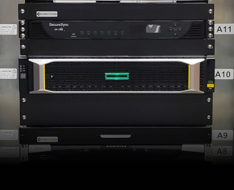
READY TO DEPLOY
RACK INTEGRATION SERVICES
Core Systems provides a wide range of high-quality open frame racks, server racks, and enclosures suitable for missions of all types. We offer integration services that involve creating a fully-configured rack cabinet system ready for deployment on the day of shipment.
- JOINT-DOMAIN SOLUTIONS
- SHORT-DEPTH DESIGNS
- DESIGNED FOR LAND, AIR, SEA & SPACE
- CYBERSPACE SECURITY
- Both COTS and Rugged Configurations
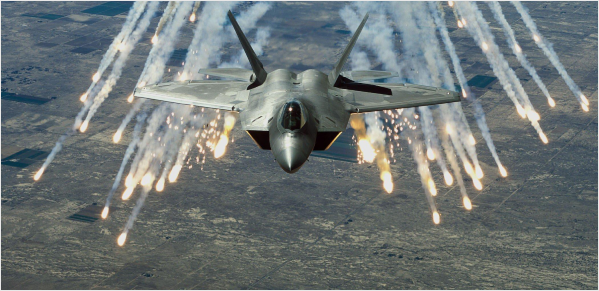
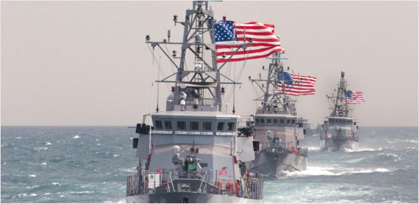
DOMAINS AND APPLICATIONS
OUR CAPABILITIES
Core Systems has a vast portfolio of work with commercial and defense programs in aerospace, transportation, military, and security and intelligence across Land, Sea, Air, Space and Cyberspace.
- JOINT-DOMAIN SOLUTIONS
- SHORT-DEPTH DESIGNS
- DESIGNED FOR LAND, AIR, SEA & SPACE
- CYBERSPACE SECURITY
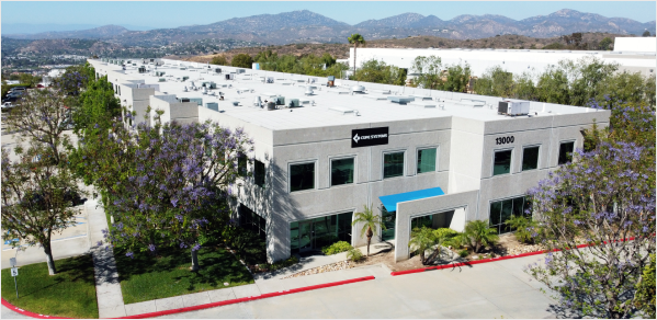
COMPANY OVERVIEW
WHO WE ARE
The Core Systems facility located in San Diego, California is one of the few vertically integrated manufacturing facilities in the nation dedicated to the production of rugged computing products.
- LOCATED IN USA
- 85,000 SQ. FT HEADQUARTERS
- METAL FABRICATION SHOP ON SITE
- COMPLETE TURNKEY SOLUTIONS